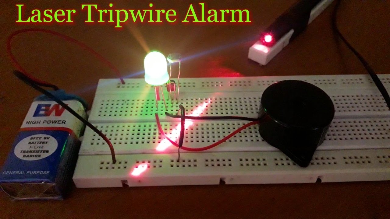
How to make a Laser Security Alarm System at Home on a Breadboard HD Circuit Diagram Enough current now flows through the circuit to trigger the gate of the SCR. Once the gate of the SCR is triggered, current now flows across from its anode to cathode and turns on the buzzer. Once triggered, the SCR stays on, just like an alarm, stimulating an alarm circuit. And this is how this light alarm circuit works.
This is where you get to control the sensitivity of your light detector. For higher sensitivity, adjust trimmer as exact as possible to the point where the LED turns off. To decrease sensitivity, turn a little ways more after the LED has turned off. CAUTION: Ensure that the LDR is not obstructed from the light source while you perform this step. 4. This simple photosensitive alarm activates a buzzer when light shines directly on the connected LDR. The system should be placed on the window at night so that when the light appears in the morning, it will activate the buzzer to alarm. The alarm makes use of a buzzer which is powered by a 9V battery. Read through to understand more. Components:

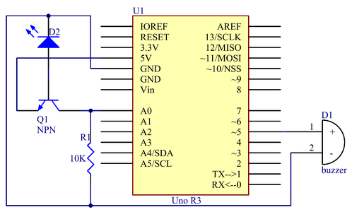
Light Alarm Circuit with LDR Circuit Diagram
The light-dependent resistor module has four pins: 3.3V : While 'VCC' stands for Voltage Common Collector, we'll connect the VCC pin to 3.3V on the micro:bit GND: In electronics, we define a point in a circuit to be a kind of zero volts or 0V reference point, on which to base all other voltage measurements. This point is called ground or GND.

In this video, we'll show you how to create a light-sensitive alarm system using Arduino. This simple yet effective DIY security project will help you detect

How to Build a Light Alarm Circuit Circuit Diagram
This musical light alarm circuit is very simple, uses only 7 components, a LDR and a 3.6 V battery or 3 x 1.2 volts rechargeable batteries. The well-known UM66 is used as the sound generator and will give a pleasent wake up alarm. As you probably know the LDR is a light dependent resistor.